Description

Note:
- Cam and Coam represent the enhanced dynamic- and static load. Their calcultions referred to the standard of DIN 69051.
- Stiff ness of nut: Stiff ness values listed above are derived from theoretical formula to the elastic deformation between thread grooves and balls while axial load is 30% dynamic load rating.

| Screw size | Ball DIA. |
Effeftive turns |
MODIFIED LOAD CAPACITY(kgf) |
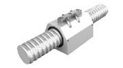
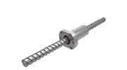
BALLNUT DIMENSION | Nut Model No. | 2D-CAD (DWG) |
|||||||||||
| O.D. | Length | Flange | Oil Hole | Assembly Hole |
STIFFNESS | ||||||||||||
| O.D. | Lead | Dynamic (1×10⁶ REV.) Cam |
Static
Coam |
D |
L |
A | T | W | G | H | Q | X | kgf/μm | ||||
| 16 | 5 | 3.175 | 3 | 1050 | 2200 | 28 | 42 | 48 | 10 | 38 | 20 | 40 | M6x1P | 5.5 | 17 | FSIN1605B-3.0P | |
| 20 | 5 | 3.175 | 4 | 1530 | 3720 | 36 | 50 | 58 | 12 | 47 | 22 | 44 | M6x1P | 6.5 | 25 | FSIN2005B-4.0P | |
| 25 | 5 | 3.175 | 4 | 1700 | 4720 | 40 | 50 | 62 | 12 | 51 | 24 | 48 | M6x1P | 6.5 | 37 | FSIN2505B-4.0P | |
| 10 | 4.762 | 4 | 2900 | 6990 | 85 | 62 | 12 | 51 | 24 | 48 | M6x1P | 6.5 | 32 | FSIN2510D-4.0P | |||
| 32 | 5 | 3.175 | 4 | 1900 | 6090 | 50 | 50 | 80 | 12 | 65 | 31 | 62 | M6x1P | 9 | 50 | FSIN3205B-4.0P | |
| 10 | 6.35 | 4 | 4720 | 11670 | 50 | 80 | 80 | 13 | 65 | 31 | 62 | M6x1P | 9 | 50 | FSIN3210F-4.0P | ||
| 40 | 5 | 3.175 | 4 | 2090 | 7670 | 63 | 54 | 93 | 15 | 78 | 35 | 70 | M8x1P | 9 | 52 | FSIN4005B-4.0P | |
| 10 | 6.35 | 4 | 5310 | 14850 | 82 | 60 | FSIN4010F-4.0P | ||||||||||
| 50 | 10 | 6.35 | 4 | 5890 | 18780 | 75 | 88 | 110 | 18 | 93 | 42.5 | 85 | M8x1P | 11 | 70 | FSIN5010F-4.0P | |